
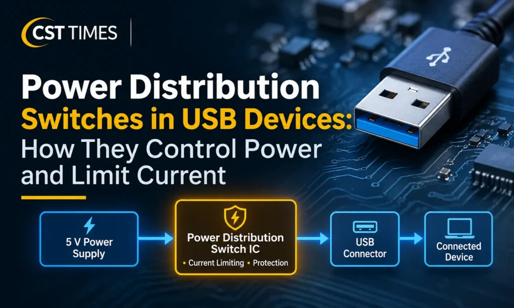
Power Distribution Switches in USB Devices: How They Limit Current
Quick Summary:
A power distribution switch is an electronic component that controls the flow of electricity between a power supply and a USB port. It uses an internal MOSFET to turn power on or off and limit excessive current when a connected device draws more than the configured threshold. Depending on its design, it can also provide short-circuit protection, thermal shutdown and fault reporting. These features help protect USB power circuits from electrical overloads. A USB power distribution switch is closely related to a load switch IC, but it is not the same as USB Power Delivery (USB PD), which handles power negotiation between compatible devices.
Table of Contents
ToggleKey Takeaways
A USB power distribution switch controls the electrical connection between a power source and a USB port.
Its internal MOSFET acts as an electronically controlled power switch.
Current limiting restricts excessive output current when a connected load creates an overload.
Short-circuit and thermal protection help manage faults that could otherwise damage the power path.
The rated output current and current-limit threshold are different specifications.
A USB power distribution switch is hardware, whereas USB Power Delivery (USB PD) is a communication and power-negotiation system.
Where a Power Distribution Switch Sits in a USB Device
A USB device needs a controlled power path to supply electricity to connected peripherals.
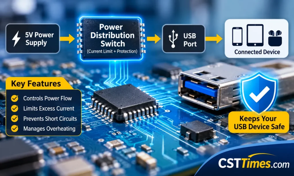
In a simple 5 V USB power system, the arrangement looks like this:
Current Limiting
Fault Protection
Simplified USB Power Distribution Path
The switch is connected in series with the power path. This means that the electricity supplying the USB port passes through the switch before reaching the connected device.
A controller can also communicate with the switch through additional control connections.
For example, an enable input can instruct the switch to supply or disconnect power. A fault output, where provided, can notify the controller when an overload or overtemperature condition occurs.
Not every USB product uses the same circuit arrangement. The number of switches, their protection features and their control methods depend on the manufacturer’s design.
Texas Instruments lists USB ports, USB hubs, laptops, desktops, high-definition televisions and set-top boxes among the applications for its TPS20xxC power-distribution switch family.
What Happens Inside a Power Distribution Switch IC?
A power distribution switch is generally built around a semiconductor power transistor and supporting control circuitry.
Its important functional elements include:
| Internal element | Main function |
|---|---|
| Power MOSFET | Connects or disconnects the power path |
| Gate driver | Controls the MOSFET’s operation |
| Current-limit circuit | Monitors output current and controls excessive current |
| Enable input | Receives an on/off command |
| Fault output | Reports specified fault conditions |
| Thermal protection | Responds when the IC becomes excessively hot |
These functions can be integrated into a single small component.
For example, Texas Instruments’ TPS20xxC family uses an internal N-channel MOSFET with a charge-pump and gate-drive circuit. It also includes controlled output rise and fall times, current limiting and fault reporting.
Some variants provide additional functions, including reverse-current blocking and output discharge. These features should not be assumed for every power switch.
This is also why understanding an integrated circuit (IC) is useful when studying power distribution components.
How the Switch Controls Power Flow
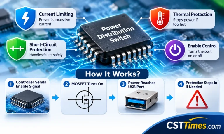
The operation can be understood through four stages.
1. The Controller Sends an Enable Signal
When a device needs to activate a USB port, its control circuit sends the appropriate signal to the switch’s enable input.
The enable pin can use active-high or active-low logic, depending on the particular IC.
When the required signal is received, the switch begins connecting the power supply to its output.
2. The Internal MOSFET Turns On
A MOSFET is a semiconductor transistor that controls current using an electrical signal.
Inside the power distribution switch, the MOSFET acts as the main electronic switching element.
When it is turned on, electricity can pass from the input supply towards the USB port. When it is turned off, it interrupts that power path.
This electronic operation allows a computer or controller to manage USB port power without a traditional mechanical switch.
3. The Output Voltage Rises Gradually
Powering a connected USB device can create a temporary increase in current.
Many peripherals contain capacitors that need to charge when power is first applied. The initial charging demand is called inrush current.
Some power distribution switches use a soft-start function to control how quickly the output voltage rises.
Rather than immediately applying the full output voltage, the circuit increases it gradually. This helps reduce sudden current demand and the possibility of a temporary power-supply voltage drop.
Texas Instruments specifies a nominal output rise time of approximately 0.55 ms for its 0.5 A and 1 A TPS20xxC versions under a particular datasheet test condition of 5 V input, 1 µF output capacitance and 100 Ω load.
This is a product-specific measurement, not a general USB requirement.
4. The Switch Monitors the Output
During normal operation, the switch allows the connected device to draw the current it requires.
If the load attempts to draw more than the protection threshold, the current-limiting circuit responds.
Depending on the switch design, it can restrict the current, lower the output voltage or disconnect the output when a protection condition is reached.
How Current Limiting Works
Current limiting is one of the most important functions of a USB power distribution switch.
Every electrical component in the power path has operating limits. A connected peripheral can create an excessive current demand because of an internal fault, an unsuitable load or a short circuit.
A current-limited switch monitors the current passing through its output.
When the current reaches its specified threshold, some devices enter constant-current mode. In this mode, they maintain the output current around the limit while the available output voltage decreases.
This is different from simply allowing the power supply to deliver more and more current.
Rated Output Current vs Current-Limit Threshold
These two specifications are easy to confuse.
Rated output current describes the current rating of a particular switch model.
Current-limit threshold describes the level at which its protection circuitry starts restricting the output current.
They are not necessarily the same number.
A real example comes from the Texas Instruments TPS20xxC power-distribution switch datasheet, revised in May 2026.
The following figures apply to the standard TPS20xxC versions at 25°C with a 5 V input.
| Rated output current | Minimum current limit | Typical current limit | Maximum current limit |
|---|---|---|---|
| 0.5 A | 0.67 A | 0.85 A | 1.01 A |
| 1 A | 1.30 A | 1.55 A | 1.80 A |
| 1.5 A | 1.70 A | 2.15 A | 2.50 A |
| 2 A | 2.35 A | 2.90 A | 3.40 A |
Source: Texas Instruments, TPS20xxC and TPS20xxC-2 datasheet, Revision I. These are the 25°C current-limit values for the TPS20xxC versions, not universal USB current ratings. The TPS20xxC-2 variants have different thresholds.
The 0.5 A example is particularly useful.
Its typical current-limit threshold is 0.85 A, even though its rated output current is 0.5 A.
This does not mean that the device should be designed to deliver 0.85 A continuously. The 0.85 A figure represents its typical protection threshold, not its normal operating-current recommendation.
The actual threshold can vary within the specified minimum and maximum values.
For component selection, this distinction is important because the designer must consider the normal load, current-limit tolerance and the capacity of the upstream power supply.
Why On-Resistance Also Matters
A power switch does not have zero resistance when it is turned on.
The resistance of its internal MOSFET affects the voltage drop and the heat generated during normal operation.
For the 0.5 A TPS2051C model, TI specifies:
Typical on-resistance: 97 mΩ at 25°C.
Maximum on-resistance: 110 mΩ at 25°C.
Using the typical resistance at a 0.5 A load:
Voltage drop
0.5 A × 0.097 Ω = 0.0485 V
That is approximately 48.5 mV.
Power dissipated
0.5² × 0.097 = 0.02425 W
That is approximately 24 mW.
These are calculated examples using the datasheet’s typical resistance, not independent laboratory measurements.
They demonstrate why engineers check both the current rating and on-resistance when selecting a power switch.
Overcurrent Protection vs Short-Circuit Protection
Both conditions can cause excessive current, but their electrical causes are different.
Overcurrent Protection
Overcurrent happens when a load attempts to draw more current than the circuit is designed to supply.
For example, imagine a USB accessory with an internal fault that causes it to demand more current than its intended operating level.
The switch detects the excessive demand and activates its current-limiting mechanism.
In a constant-current design, the output current is restricted and the output voltage can fall as the load resistance decreases.
Short-Circuit Protection
A short circuit occurs when an unintended low-resistance connection creates a direct or nearly direct path between power and ground.
For example, a fault inside a USB device might connect the 5 V power line to ground.
This can produce a rapid increase in current.
A power distribution switch with suitable short-circuit protection can limit that current and help prevent the fault from placing excessive stress on the upstream power supply.
The specific response depends on the IC.
What Happens When the Fault Continues?
Current limiting does not mean that the switch can dissipate unlimited power.
During a persistent short circuit, the switch may have to maintain current while dropping most of the input voltage across its internal power transistor.
That generates heat.
This is why many power distribution switches also include thermal protection.
For example, the TI TPS20xxC family uses thermal cycling during a sufficiently persistent overload:
The switch limits output current.
The internal temperature increases as power is dissipated.
The thermal protection switches the output off.
The device restarts after its junction temperature cools by the specified hysteresis amount.
TI documents a 135°C thermal-shutdown threshold while operating in current-limit mode and describes restart after 20°C of cooling for this family.
This behaviour should not be assumed for every power distribution switch.
Different ICs Can Respond Differently
Manufacturers use different fault-handling strategies.
| Protection behaviour | What happens |
|---|---|
| Constant-current limiting | Output current is held near the current-limit threshold |
| Latch-off | The output switches off and requires a reset or control action |
| Automatic retry | The switch periodically attempts to restore power |
| Thermal shutdown | The output is disabled when the IC becomes too hot |
| Thermal cycling | Power switches off and returns after cooling |
For comparison, Analog Devices’ MAX8586 documentation describes a design that can latch off after a short circuit persists for more than 20 ms. Its selectable automatic-restart feature can test the output with a 25 mA current and restore operation when the short is removed.
This is different from the thermal-cycling behaviour documented for TI’s TPS20xxC family.
The important lesson is that a power distribution switch does not have one universal fault-response method. The exact datasheet determines what happens.
Power Distribution Switch vs Regular Electrical Switch
Both types of switches control the flow of electricity, but their capabilities are different.
| Feature | Regular mechanical switch | USB power distribution switch |
|---|---|---|
| Power on/off | Yes | Yes |
| Control method | Mechanical operation | Electronic control |
| Internal MOSFET | Not required | Used in semiconductor designs |
| Current monitoring | Not inherently included | Available in protection-oriented models |
| Current limiting | Not inherently included | Available |
| Fault reporting | Not normally included | Available on selected ICs |
| Thermal protection | Separate protection may be needed | Available in selected ICs |
| Soft start | Not normally included | Available in selected ICs |
A mechanical switch generally opens or closes an electrical connection.
A power distribution switch can perform the same basic task electronically while adding current monitoring, protection and fault-reporting capabilities.
A fuse or circuit breaker is also a protective device, but it is not the same component as a power distribution switch.
Power Distribution Switch vs Load Switch IC
The terms are related and can overlap.
A load switch IC is a broad category of electronic component used to connect or disconnect power to an electrical load.
It is commonly used to control power rails for individual circuits, sensors, displays and other electronic subsystems.
A power distribution switch is designed for managing power delivery to one or more downstream loads. USB-oriented models commonly combine electronic switching with features such as current limiting and short-circuit protection.
The distinction is not an absolute industry-wide naming rule.
For example, Texas Instruments includes power-distribution switches within its wider load-switch portfolio. Its general load-switch documentation also explains that protection features vary between different designs.
A practical way to understand the relationship is:
Load switch IC: The wider component category.
Power distribution switch: A power-switching implementation for distributing and managing power.
USB power switch: A device designed for a USB power path, often with additional USB-related protection.
Always check the actual functions in the manufacturer’s datasheet rather than relying on the product name alone.
Power Distribution Switch vs USB Power Delivery
A power distribution switch and USB Power Delivery (USB PD) perform different functions.
A power distribution switch is a physical hardware component that controls the electrical power path.
USB PD is a communication protocol that allows compatible USB-C devices and power sources to negotiate supported power levels.
Consider a 5 V USB-C source-only port that does not support USB PD.
According to Texas Instruments’ USB Type-C engineering guide, such a design can use a Configuration Channel (CC) controller to advertise supported current levels. These include default USB current, 1.5 A and 3 A at 5 V.
The same design can use a separate 5 V load switch in its VBUS power path.
The two components therefore have different responsibilities:
| Function | Power distribution switch | USB Power Delivery |
|---|---|---|
| Type | Hardware IC | Communication protocol |
| Main purpose | Control and protect the power path | Negotiate supported power delivery |
| Main connection | Electrical power path | USB-C communication channel |
| Current protection | Available in suitable designs | Source power architecture must implement protection |
| Voltage negotiation | Not its main function | Yes |
A USB-C connector does not automatically mean a device supports USB PD.
Likewise, using a power distribution switch does not mean a product has USB PD support.
A USB PD-enabled product may use separate power-path switching components alongside its PD controller. Texas Instruments illustrates this arrangement in its USB-C system-design documentation.
Where Are USB Power Distribution Switches Used?
These components are useful wherever electronic equipment needs controlled power distribution to USB ports.
Common applications include:
USB hubs: A hub can use individual power-switch channels to control its downstream ports. This can help manage a fault on one port without necessarily interrupting all other ports, depending on the design.
Computers and laptops: USB power switches can manage and protect power connections for peripheral devices.
Docking stations: Multiple USB connections make controlled power distribution useful.
Televisions and set-top boxes: Protected power paths can supply compatible USB accessories.
Communication equipment: USB power switching can be used in products that supply power to connected peripherals.
These are documented application categories, not a claim that every product in these categories uses a dedicated power distribution switch.
What to Check in a Power Distribution Switch Datasheet
For anyone comparing or selecting these ICs, the datasheet provides the most important technical information.
Use this checklist:
| Specification | Why it matters |
|---|---|
| Input voltage range | Confirms the supported supply voltage |
| Rated output current | Shows the device’s specified output-current class |
| Current-limit threshold | Identifies when current protection activates |
| Current-limit tolerance | Shows how much the actual threshold can vary |
| On-resistance | Affects voltage drop and power dissipation |
| Response time | Describes how quickly the IC responds to specified faults |
| Output rise time | Helps evaluate inrush current control |
| Thermal shutdown | Describes protection against excessive temperature |
| Fault output | Shows whether a controller can receive fault information |
| Reverse-current blocking | Helps prevent unwanted current flow back towards the input |
| Recovery behaviour | Identifies whether the device latches off or retries after a fault |
Two specifications deserve particular attention.
First, do not confuse rated output current with the current-limit threshold. Both affect how the device performs, but they describe different operating conditions.
Second, check the minimum and maximum current-limit values rather than relying only on the typical figure.
This helps determine whether the selected device can handle the normal load without unnecessary protection trips and whether it can protect the upstream power system.
Final Thoughts:
Power distribution switches are important components in USB power-management systems because they do more than connect and disconnect electricity.
They control the power path, restrict excessive current and can respond to short circuits and overheating. Additional functions, such as soft start, fault reporting and reverse-current blocking, depend on the particular IC.
One of the most important specifications to understand is the difference between rated output current and the current-limit threshold. A switch rated for 0.5 A does not necessarily activate its current-limiting function at exactly 0.5 A.
It is equally important to distinguish the physical switch from USB Power Delivery. USB PD manages power negotiation, while the power switch controls the electrical path.
Understanding these differences makes USB power-distribution circuits and their protection functions much easier to follow.
FAQs
Does every USB port use a power distribution switch?
No. Manufacturers use different power-management and protection architectures. Some designs use dedicated USB power-switch ICs, while others integrate the necessary functions into larger power-management components.
Does a USB power distribution switch increase charging speed?
No. Its primary function is controlling and protecting the electrical power path. It does not independently increase the power available from a charger or negotiate a faster charging level.
Can a power distribution switch protect against a short circuit?
Suitable models can limit excessive current or disconnect the output when a specified fault occurs. The actual response depends on the component’s design and protection features.
Is a power distribution switch the same as a fuse?
No. A switch with current limiting provides electronic control and can report faults or recover after a fault. A conventional fuse is a separate protective device. A product may require additional protection depending on its design.
What happens when a USB port draws more current than its limit?
A current-limiting switch can restrict the current and allow its output voltage to fall. If the fault continues, it may shut down because of thermal protection. Other models may latch off or use automatic retry.
Does USB Type-C require USB Power Delivery?
No. USB Type-C ports can operate at 5 V without USB PD. They can advertise supported current levels through their CC connections. USB PD is used when compatible devices need to negotiate additional power capabilities.
Can a power distribution switch work alongside USB Power Delivery?
Yes. They perform different functions and can exist in the same product. The PD controller manages negotiation, while separate power-path hardware manages switching and electrical protection.
Disclaimer
This article is for educational and informational purposes only. Electrical characteristics and protection behaviour vary by component and product design. Always consult the manufacturer’s latest datasheet and follow appropriate electrical safety requirements before designing, modifying or repairing USB power circuits.
